By Suneco Lighting
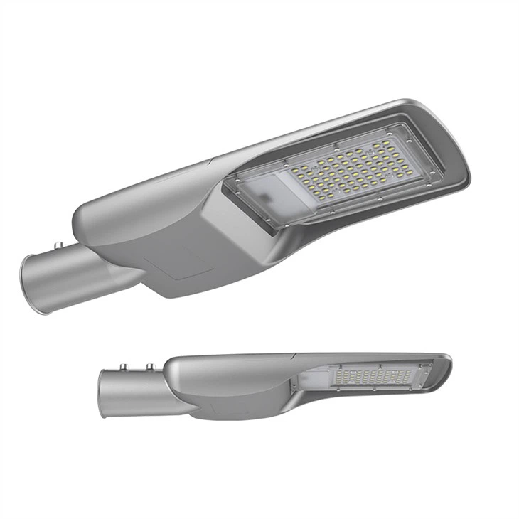
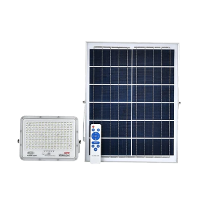
All in one solar street light pole spacing controls how evenly light reaches the road. Suneco Lighting recommends using a photometric layout for the proposed integrated model instead of a universal spacing-to-height ratio.
Contents
- 1 Define the Road-Lighting Requirement
- 2 Review the Complete Product Configuration
- 3 Compare Technical Evidence
- 4 Avoid Common Selection Errors
- 5 Check Performance in Real Conditions
- 6 Coordinate Pole, Electrical and Civil Work
- 7 Use Samples and Acceptance Tests
- 8 Evaluate Lifecycle Cost and Support
- 9 Control Project Documents and Revisions
- 10 Buyer Checklist
- 11 FAQ
Define the Road-Lighting Requirement
Begin the all in one solar street light pole spacing review with measurable project inputs. Catalogue values help shortlist products, but the approved design should connect the site geometry, performance target, environment and operating policy. Record assumptions so that every supplier answers the same brief.
- Road width, lanes, bends and intersections.
- Mounting height and allowable pole locations.
- Luminaire photometric file and tilt.
- Target average, minimum and uniformity.
- Trees, buildings, utilities and panel shade.
Mark missing information as a design hold point. A preliminary recommendation can use stated assumptions, but final model selection, quantity and price should reference the approved drawings and performance schedule.
Review the Complete Product Configuration
The all in one solar street light pole spacing proposal must identify the complete configuration rather than a wattage or catalogue family. Review the following items together because a change to one item can affect photometry, structure, electrical protection, installation or warranty.
- Integrated luminaire with known distribution.
- Pole-top or side-entry mounting bracket.
- Structurally suitable pole.
- Foundation matched to site soil and wind.
- Installation setting and aiming record.
Ask the manufacturer to reference exact model codes on drawings, data sheets, certificates and the quotation. Matching document references reduce the risk of approving one configuration and receiving another.
Compare Technical Evidence
Use one compliance schedule for every bidder. Require a clear response, deviation and supporting document for each line. Do not award points for unverified claims or assume that a higher headline number automatically improves road performance.
| Review item | Meaning | How to verify |
|---|---|---|
| Narrow path | Lower mounting | Closer pedestrian spacing |
| Local street | Moderate height | Roadway distribution |
| Wide road | Higher output review | Multiple-row options |
| Curve | Changing sight line | Closer local spacing |
| Junction | Conflict area | Dedicated layout |
When an alternative is proposed, show its effect on energy use, lighting results, pole loads, installation work and maintenance. This allows buyers to consider value engineering without losing the original acceptance criteria.
Avoid Common Selection Errors
Projects involving all in one solar street light pole spacing often fail because commercial comparisons begin before technical assumptions are aligned. Check the following risks during design review and again before purchase.
- Using maximum spacing from a brochure.
- Raising poles without checking useful output.
- Tilting fixtures to create glare.
- Placing poles where panels are shaded.
- Ignoring curves and junctions.
Resolve each exception in writing. The approved sample, technical schedule and purchase order should use the same revision so the production team and inspector know what must be supplied.
Check Performance in Real Conditions
Outdoor LED equipment operates through voltage variation, high and low temperatures, rain, dust, vibration and pollution. Review rated values together with test conditions and expected maintenance. Confirm how thermal limits, lumen depreciation and driver life affect the chosen operating point.
Road-lighting calculations should use the exact IES file, mounting geometry and maintenance factor. If the site changes, update the calculation instead of relying on the original result. Intersections, pedestrian crossings, curves and conflict zones may require separate checks.
Coordinate Pole, Electrical and Civil Work
The luminaire, pole, arm, anchor system, foundation, cables, protective devices and earthing form one installation. Define who supplies and installs each item. Confirm spigot dimensions, cable lengths, access-door position, circuit protection and foundation reactions before manufacturing starts.
Where existing poles or circuits are reused, inspect their condition and compatibility. Record any adapter, rewiring or reinforcement work in the supply scope instead of leaving it for site improvisation.
Use Samples and Acceptance Tests
Approve a representative sample with the actual LED board, driver, optics, surge device, housing finish and mounting parts. Record labels and component codes. Production inspection should compare units with that approved sample and the controlled bill of materials.
Factory checks can include power, power factor, safety, dimming, surge-component verification, dimensions, finish and photometric reports. Site acceptance should confirm installation, aiming, controls and measured lighting results under agreed conditions.
Evaluate Lifecycle Cost and Support
Compare purchase price with energy, installation, inspection, access equipment, cleaning and replacement parts. Define the warranty claim process and ask which modules can be replaced locally. A documented spare-parts plan can reduce downtime more effectively than a long but unclear warranty statement.
Request operating instructions, wiring information, driver programming details and test records. These documents support future maintenance and reduce dependence on informal knowledge.
Control Project Documents and Revisions
Keep one document register for the quotation, data sheets, IES files, calculations, drawings, certificates, inspection records and packing list. Each item should show a revision and approval status. When a model, optic, driver, arm or operating schedule changes, identify which calculations and drawings must be updated. This prevents an early sales document from being mistaken for the final production specification.
Before shipment, assemble a handover file that links serial or batch information with the approved configuration. The installer should receive current foundation details, wiring diagrams, aiming or programming instructions and a contact route for technical questions. Clear revision control protects the buyer, manufacturer and contractor during installation and warranty service.
Buyer Checklist
- Freeze road geometry and measurable lighting targets.
- Reference exact models, optics, drivers and mounting parts.
- Compare bids with one compliance and deviation schedule.
- Approve a representative sample before mass production.
- Confirm inspection, packing, delivery and warranty duties.
FAQ
Is there one correct spacing ratio?
No. Optics, output, road width, mounting height and uniformity determine spacing.
Does a taller pole always allow wider spacing?
Only if useful light and minimum levels remain acceptable.
How does the solar panel affect placement?
The panel needs a clear solar window, which may conflict with trees or structures.
Should the light be tilted?
Use the photometric layout and glare limits; excessive tilt often reduces visual comfort.
What drawing should installers receive?
Provide pole coordinates, height, orientation, foundation and controller settings.
Send Suneco Lighting your road plan, performance target, pole details, quantities and delivery destination. Our team can review the all in one solar street light pole spacing requirements and prepare a clear technical and commercial proposal.

Get Best Suneco Solar Lighting
Join the Suneco Lighting Newsletter for solar light updates, buying guides and project advice.